Dragon
General Overview
Meet Dragon, Desert WAVE's second AUV. Dragon was designed to work in conjunction with Phoenix. She will have all the capabilities that Phoenix does, as well as a pneumatic system that allows for advanced manipulation.
The content on this page documents the individual designs that were implemented, as well as, the testing conducted throughout the development process which brought Dragon to life.
Mechanical

Hull Design
Unlike Phoenix, Dragon's overall design includes five hulls: the thruster hull, the pneumatics hull, the computer hull, and two battery hulls. Separating these major systems into different hulls reduced the overall design complexity of each hull. The modularity of the design also allows members to remove any one hull from the frame without disturbing the rest of the AUV sub-systems.
Marker Dropper
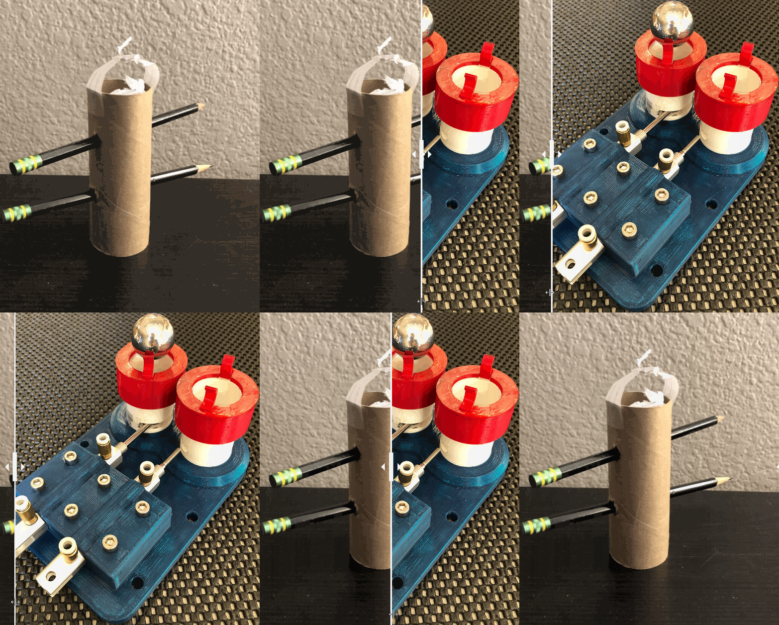
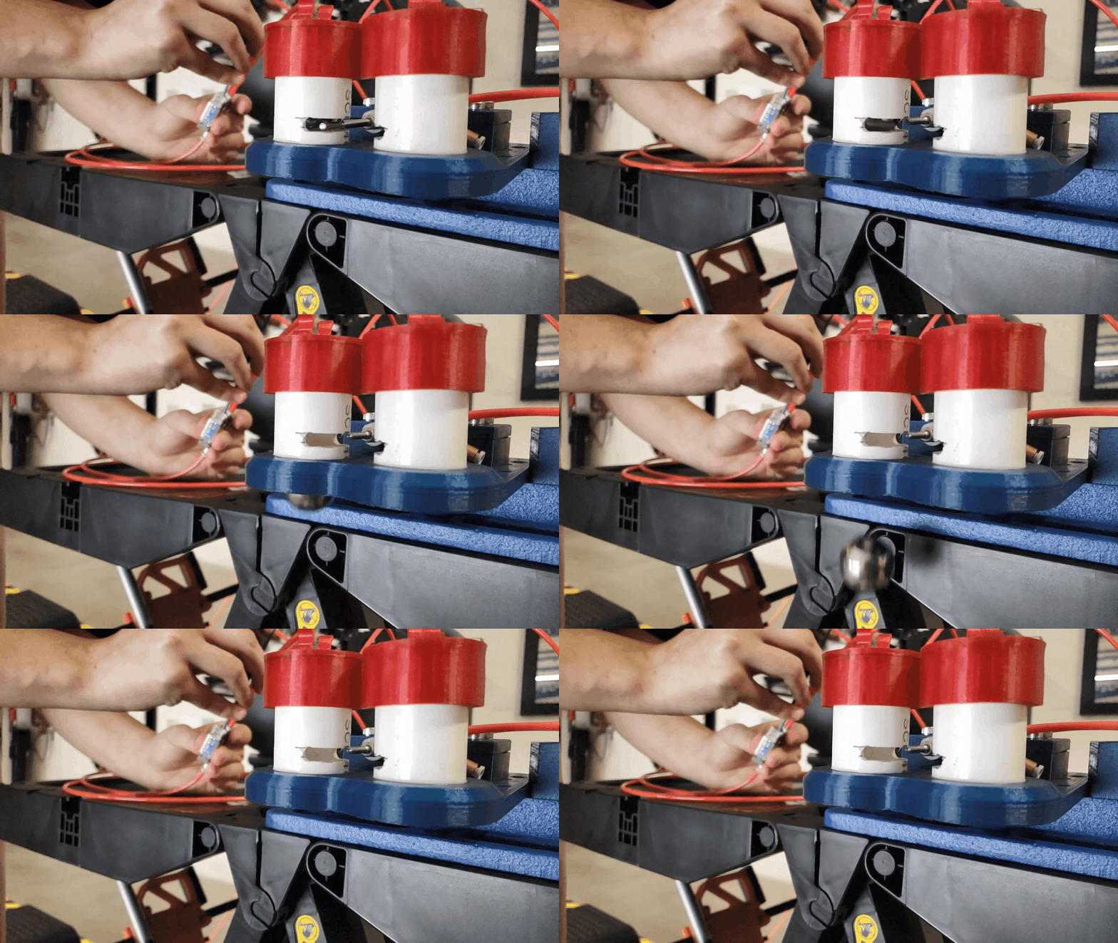
Dragon’s marker dropper was designed to be simple, reliable, and efficient. The initial prototype was constructed with a cardboard tube and pencils. The next iteration of the design was made of PVC pipe and 3D printed parts. The red tabs allow the markers to be easily loaded with one hand. Pneumatic pistons release the markers with 1 in of movement. The marker dropper had a perfect first trial run.

Projectile Launcher
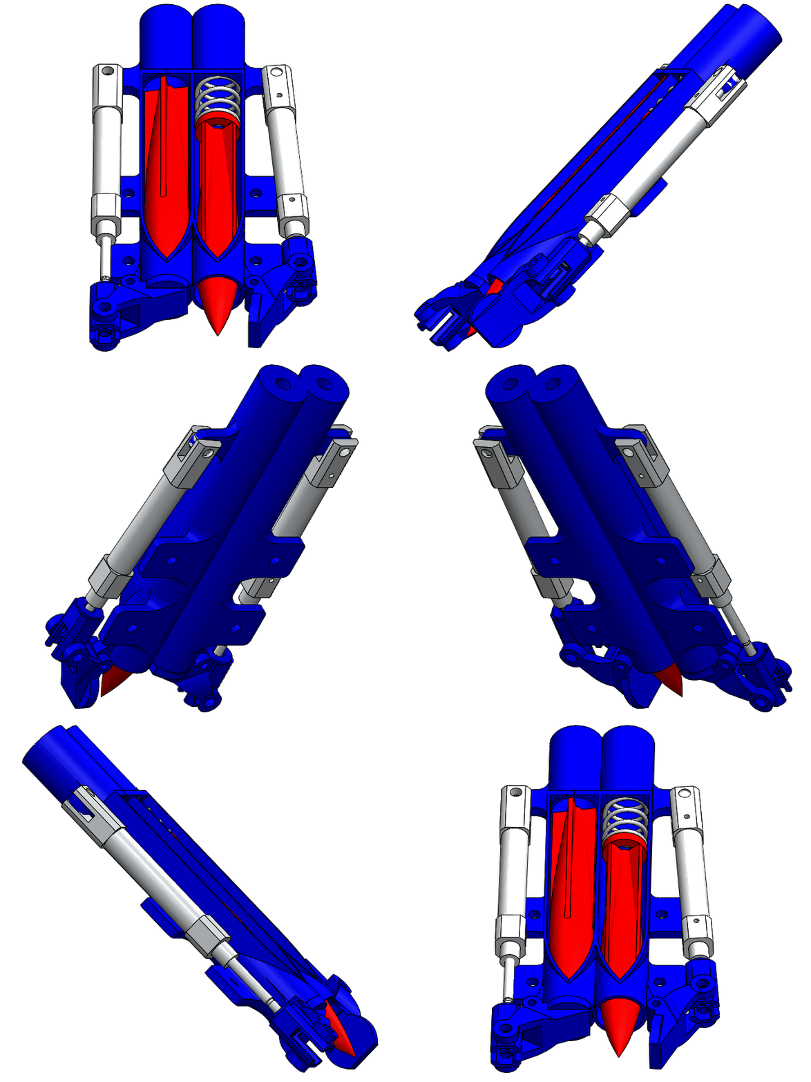
The projectile launcher is 3D printed, easily loaded with one hand, and actuated by a pneumatic piston with 1 in stroke. When the projectile launcher is loaded into the bay, a spring is compressed behind the projectile. When a piston opens the hatch that restrains the projectile, the pressure is released and the spring propels the projectile forward. Testing has shown the projectile will travel in a straight path for approximately 1 m and has a nearly neutral buoyancy.
Grabber
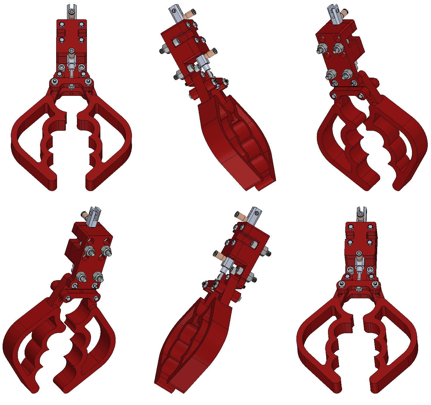
Dragon is fixed with a pneumatic grabber arm purposed to pick up objects underwater. Its design was inspired by Team Bumblebee from Singapore. The pneumatic piston moves with a 1-inch stroke of movement allowing the grabber claws to open 3.5 inches wide. The grabber arm can be mounted horizontally or vertically. The grabber had a successful first trial run.
Electrical
Customized Boards:

Mainboard
The Mainboard communicates similarly to the Main Board on Phoenix, by sending sensor information to the Jetson. The Jetson is an Embedded AI computing device that handles higher-level tasks such as mission management, outer control loops, network communications, vision processing, and data logging.
Motor Control Board
To control the motors, the Mainboard runs the control loops that determine motor values based upon the given set points/inputs; this is dependent on which control mode is active. Motor values are sent to the Motor Control board, and these values are translated into PWM signals that are used to manage the motors.


Sensor Fusion Board & Fiber Optic Gyro
While Phoenix utilized a single-axis FOG (Fiber Optic Gyroscope), Dragon was upgraded to a three-axis. The Sensor Fusion Board receives data from the FOG and DVL, this data provides a sensor fusion algorithm to generate yaw, pitch, and roll. This process generates a more consistent, accurate, and dependable source of information needed to complete game tasks.
Pneumatics Board
The Pneumatics Board is used to control Dragon’s 8 solenoids. This board receives a command from the main board indicating which actuator to enable, during this process, telemetry data is sent back to the Main Board. This is accomplished by an N-channel MOSFET connected to each solenoid, in a low side switching configuration.

Software Testing

HSV Model
For vision software, the team first began writing code to detect objects of a certain color, such as a red circle, using OpenCV and a hue, saturation, value filtering technique (right).
The team then began writing software to detect more complicated shapes, like path markers, from footage from the previous competition (left).
Machine Learning Model
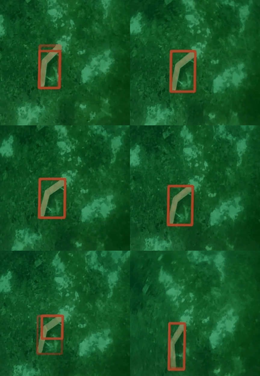
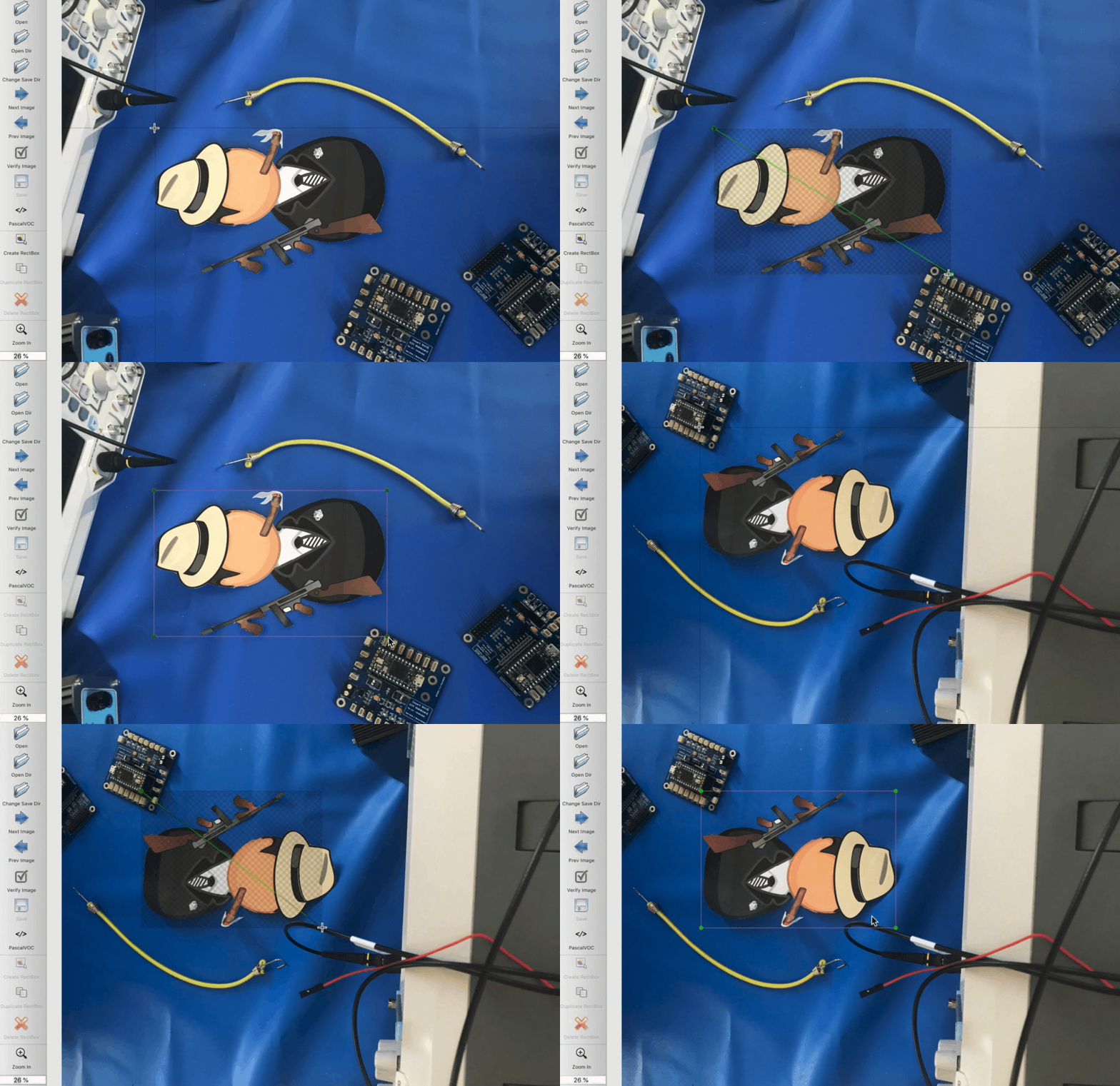
The team then began writing software to detect more complicated shapes using a convolutional neural network. The image to the left shows a member annotating an object in different orientations.
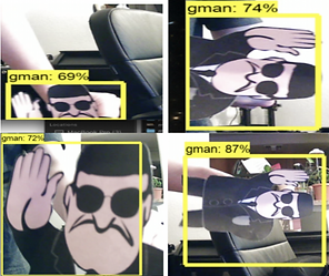
The more data introduced to the model, the higher the confidence level that is produced. The image to the right shows a progression of accuracy in detecting the object after introducing a variety of data to the model.
Simulation Testing
AUV Operator Interface
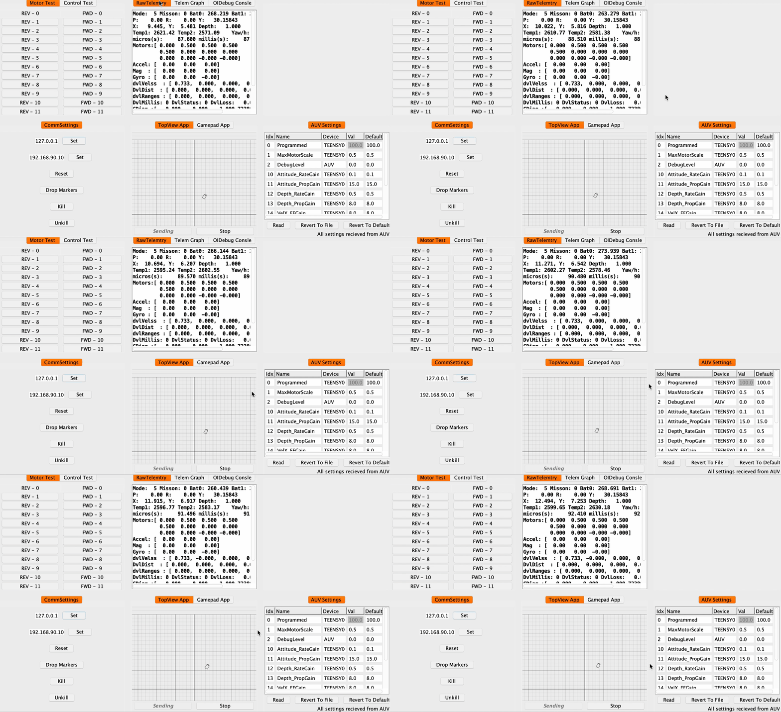
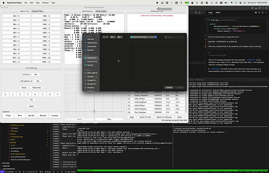
The testing simulator allows the team to test the ability of the AUV to navigate to a certain position determined by user input. One module reports telemetry data, while another is used to send the operation mode. Currently, work is being done to upgrade the simulator to allow the team to be able to test vision software prior to entering the water.
Unity
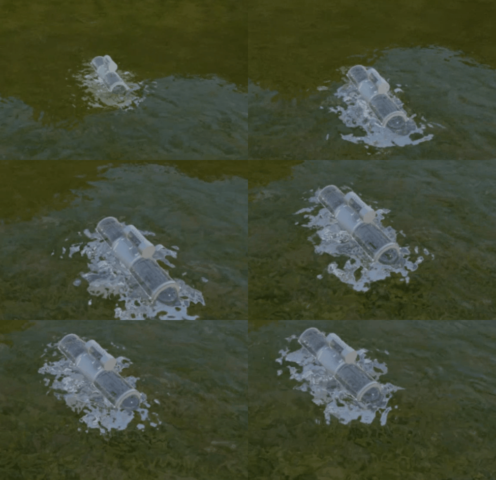
When we're not able to test in the water, we have a Unity-based 6 degree of freedom simulator that uses a physics model of the AUV to determine how it will react to motor efforts determined by simulated sensor readings.
AUV Simulated Navigation
Prior to testing Dragon in the water, the team programs a simulation of the AUV's navigation process. The AUV navigates to the task area and takes a picture of the bin to analyze the red color. The AUV moves closer to the red area and drops the marker to complete the task.
Water Testing
Color Testing
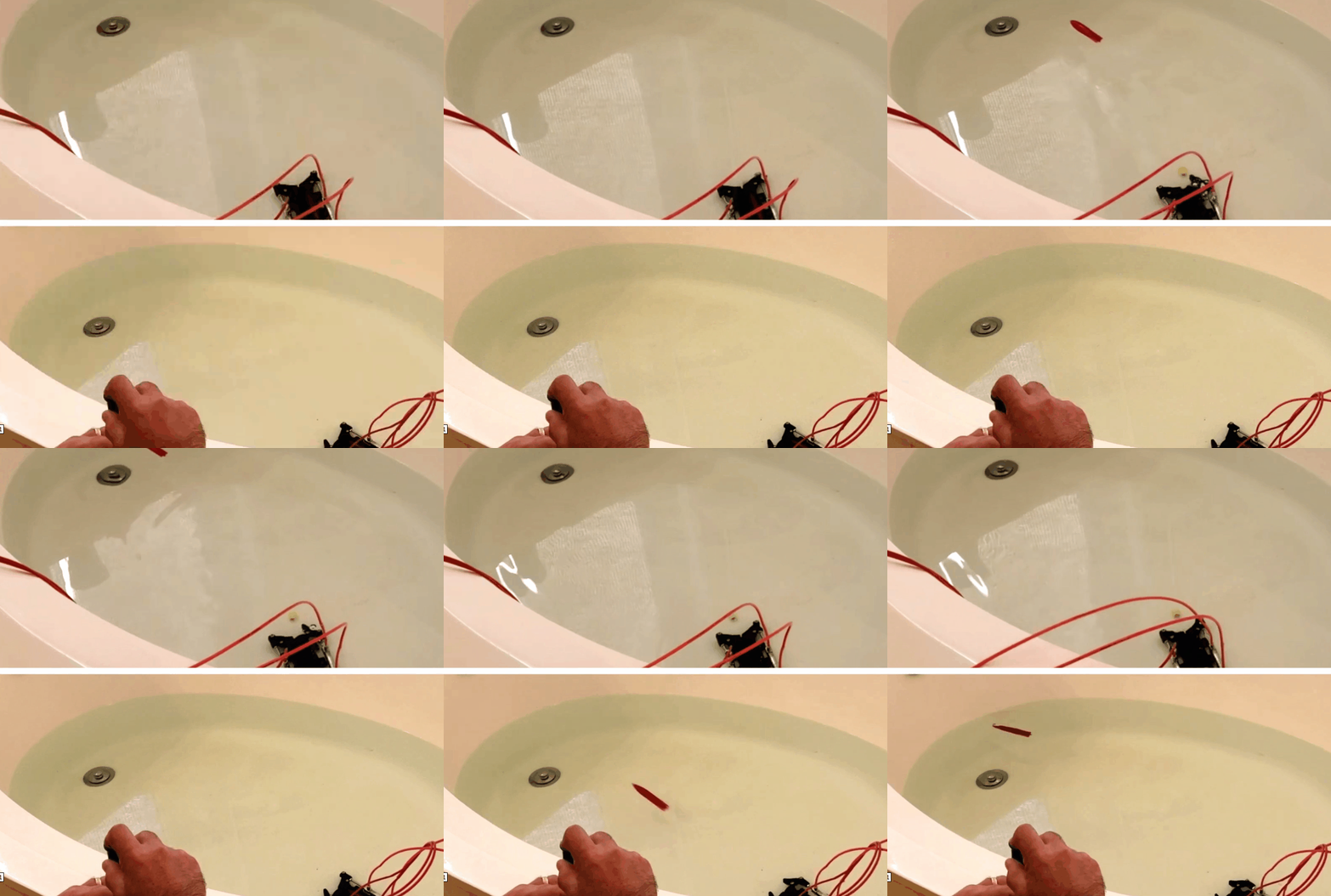
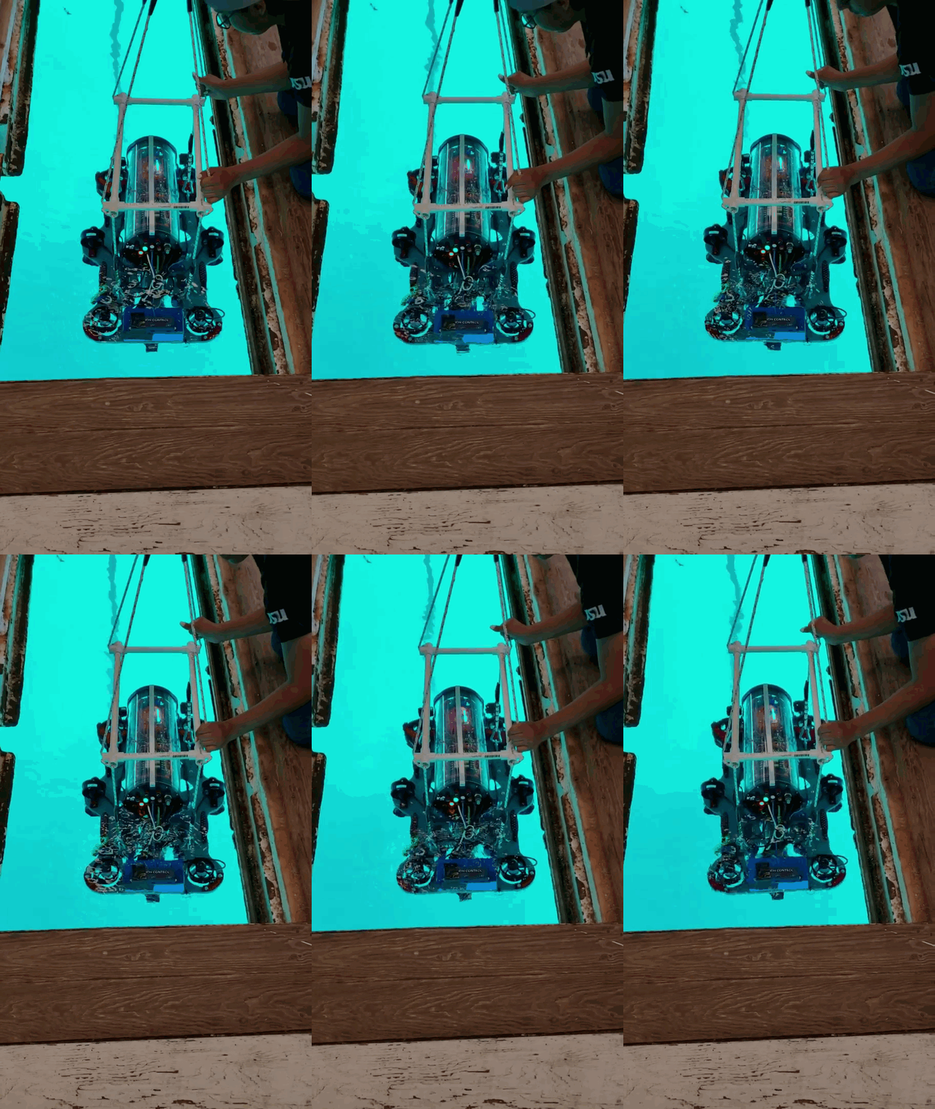
Dragon was tested in the water to test its ability to tell different colors apart. Using a bin colored with a red and blue side, the team gives the AUV instructions to drop a marker over the red region. The AUV successfully completes its task.
Misc. Testing
Grabber Arm Testing
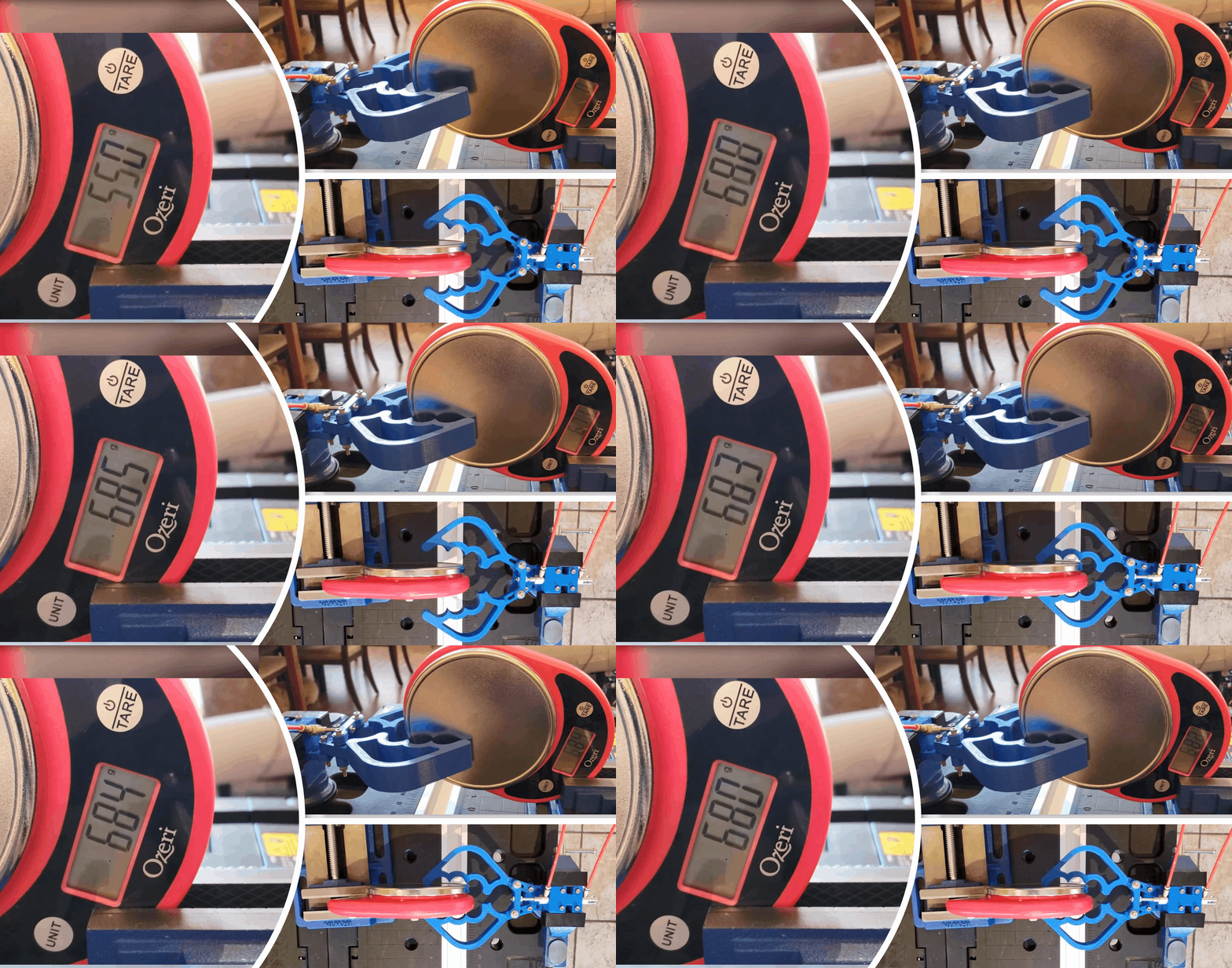
The grabber’s grip strength is essential to the AUV’s ability to pick up objects. The grabber was tested by picking up wooden blocks.
Torpedo Testing
Testing showed the projectiles launched straight forward, but rose to the surface almost immediately due to their buoyancy. More projectiles were printed at greater infill percentages until a nearly neutral but slightly positive buoyancy was achieved.
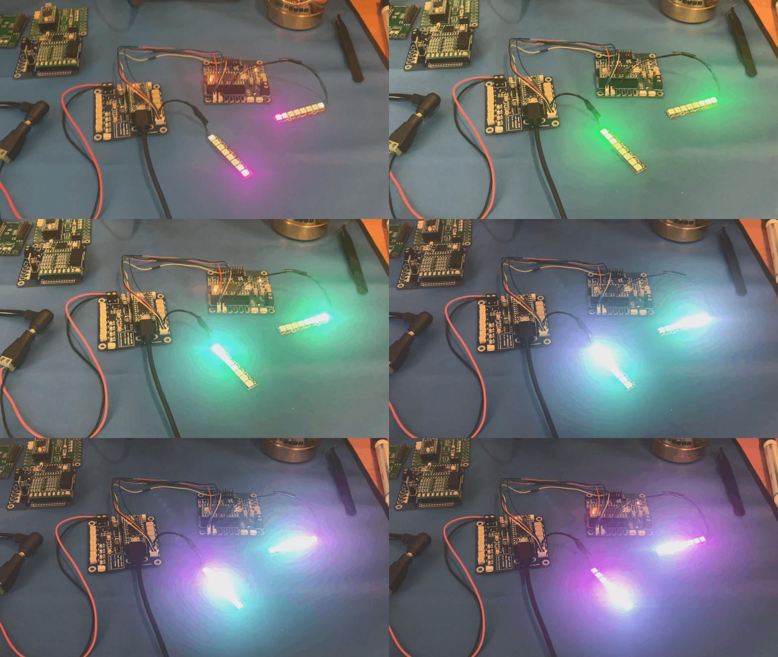
Board Communication Testing
The Mainboard (left) sends the current control mode to the Motor Control board (right) and it’s LEDs will mimic the mode that is defined on the Mainboard. The mimic in LED color and pattern indicates information is received.
Hydrophone Testing
A Subsonus hydrophone array was used to collect acoustic data at the TRANSDEC facility. The Subsonus unit is made up of an 8 hydrophone array. The data obtained from the TRANSDEC facility will be used as a baseline to adjust for noise further testing.
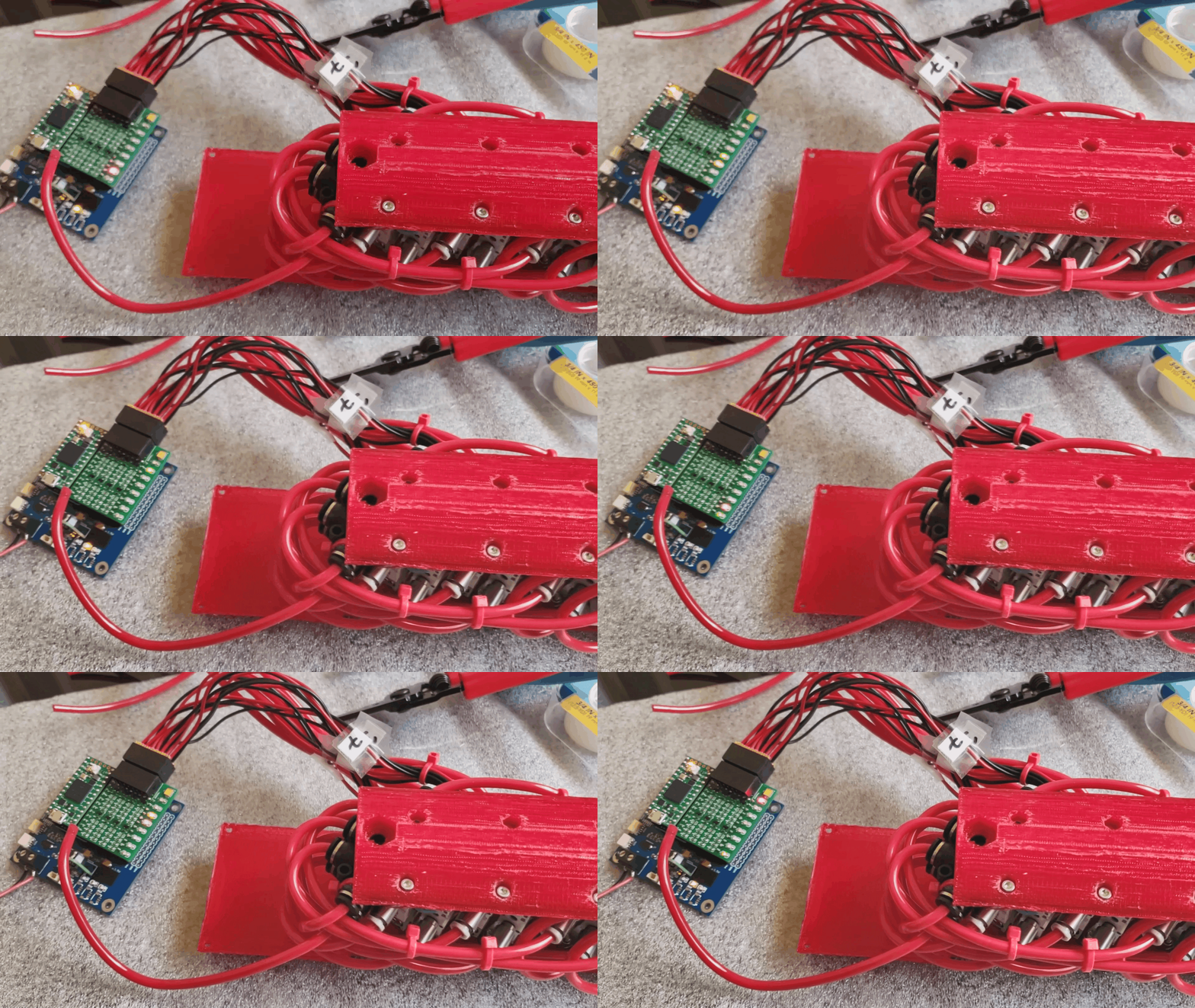
Solenoid Test Program
The marker dropper, torpedo launcher and grabber arm all utilize pneumatic cylinders operated by solenoids. The solenoids receive signals from the custom pneumatics board (see Mechanical section). This photo shows leds lighting to depict each solenoid firing during a testing of a program that was designed to test fire each solenoid one-by-one.
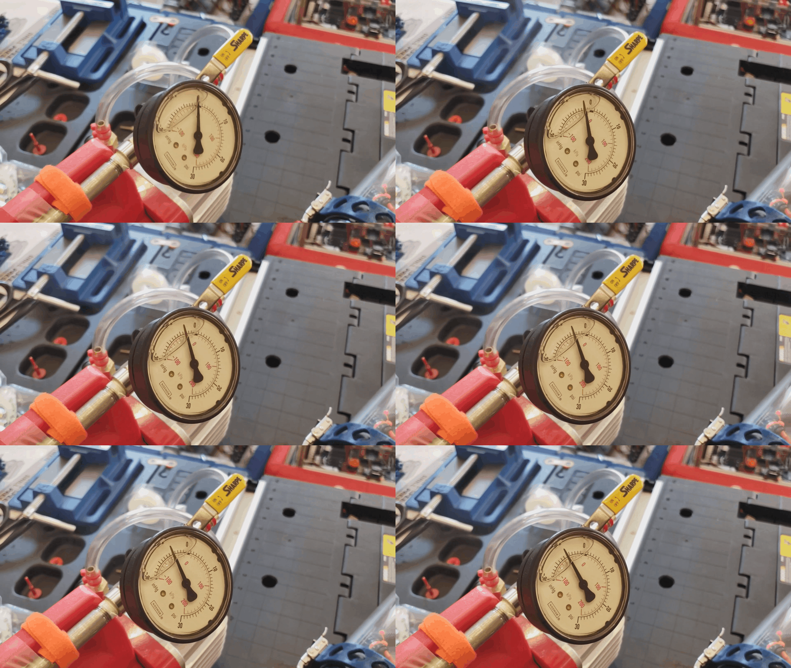
Vacuum Leak Test
Each hull put through a two-step watertight testing process before it is mounted to the AUV frame. The first step checks for leaks via a vacuum test. The second step requires the hull to be submerged in water and visually inspected. In the event of a leak during a mission, the modular design of the hulls contain the damage to only one system.
Marker Dropper Testing
The marker dropper was designed to be easily accessible and loaded quickly. The piston of the solenoid supports the payload until a signal is received to release it. The marker has been tested dozens of times without fail.
3D Print Test
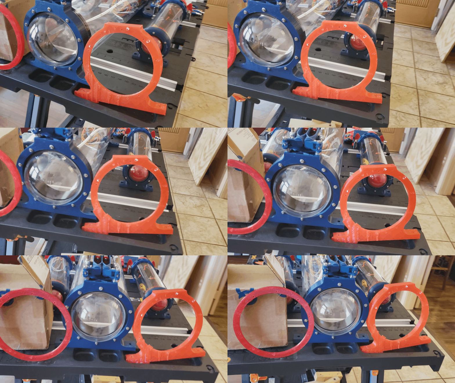
All large 3D printed components were first manufactured as low-density draft prints to test fit and functionality before being printed at higher infills in their final form.


